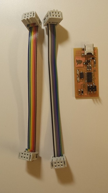
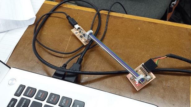
I started this week by fixing some of the problems from past weeks; I created a new FabISP programmer board and two new IDC ISP cables. They both worked perfectly!
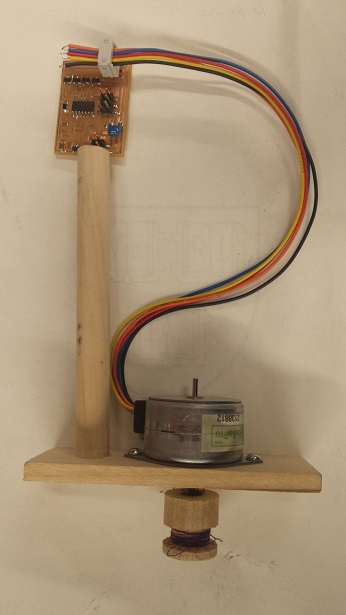
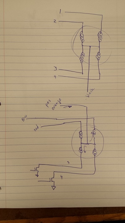
Rob gave me an overview of all kinds of output devices that we have in the lab. I have chosen to use the unipolar stepper motor as a possible component for my final project, because I would need a motor that can turn to a specific location. This is the example of a unipolar stepper motor that I have been trying to follow this week:
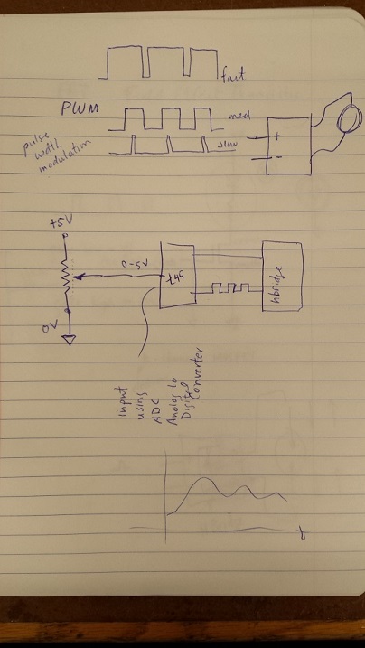
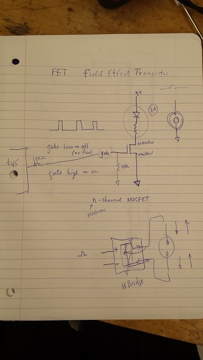
Rob also explained to me what pulse width modulation (PWM) is and how Field Effect Transistors (FETs) work. He also showed me how the inside of a unipolar stepper motor looks like:
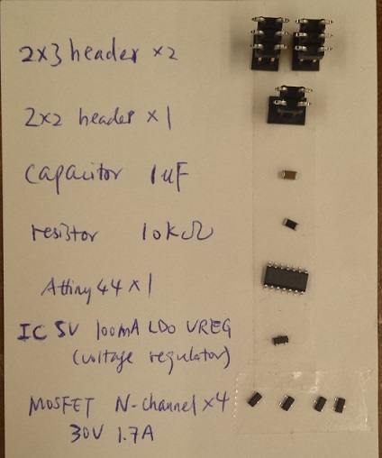
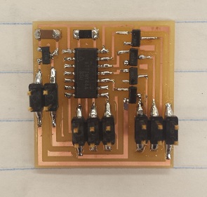
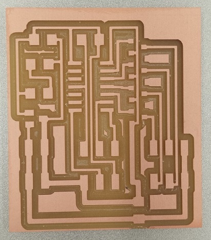
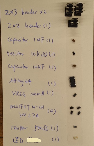
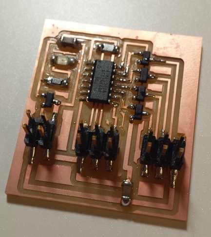
Rob suggested that I use Neil's example board for unipolar stepper motors first before trying to create my own. So I started off by milling Neil's board found on our class webpage. Here is the list of components on this board and the finished board:
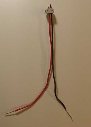
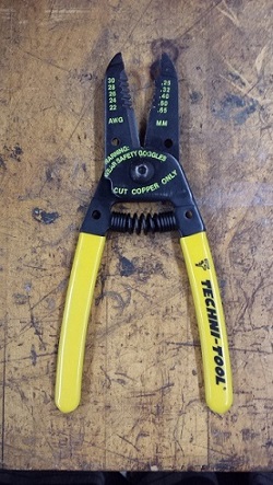
I also asked Vincent for help. He showed me how to create a 2x2 header to power the board. I had to decide where to insert the red and black wires based on the design of the board, and use a snapper wire cutter (in this case, the 0.65 mm hole) to remove some of the plastic casing to expose the metal part. Here's a picture of the header and the tool I used:
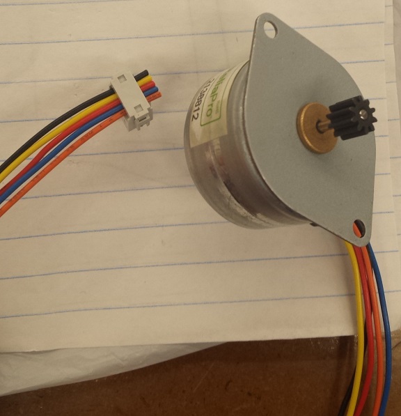
I also followed Rob's example motor and inserted the colored wires into a 2x3 header to make the motor ready to connect to the board.
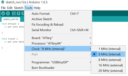
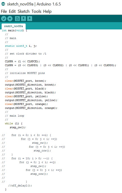
Vincent also showed me how to use Neil's C code (also can be found on this week's page) in Arduino to program the board. Since the microcontroller on this board did not use an external clock, we changed the setting for the clock to "8 MHz internal":
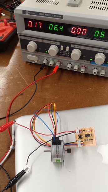
The motor did turn; but there were a couple of problems that I observed:
The video below illustrates these problems. I tried to change the voltages and measure the temperature of the MOSFETs:
Rob helped me debug the board. I tried replacing one of the MOSFETs which looked burnt from the outside; but the problem still persisted. We tried to compare his example board with the board I made, and noticed that in Rob's example board there was an extra load capacitor that was added between the VCC and the GND to remove noise. So we decided to give that a shot and add an extra 10uF capacitor to the board (on the lower right hand side of the board):
And this capacitor did the magic! The problem was resolved: the MOSFETs did not turn warm or hot at higher voltages, and the motor kept rotating even at higher voltages. Here's a video of motor in motion after the modification. The temperature of the MOSFETs stayed below 100 oF throughout:
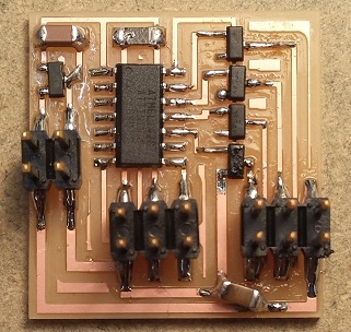
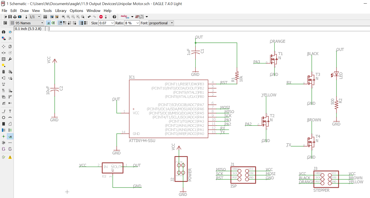
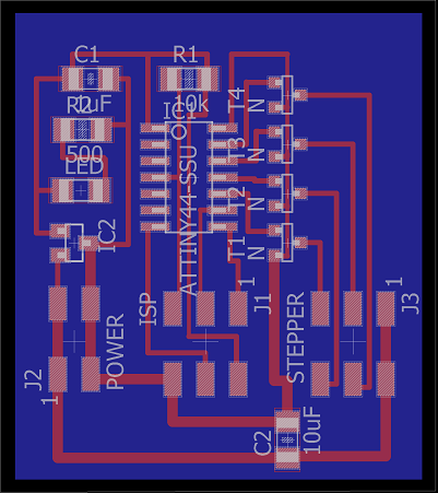
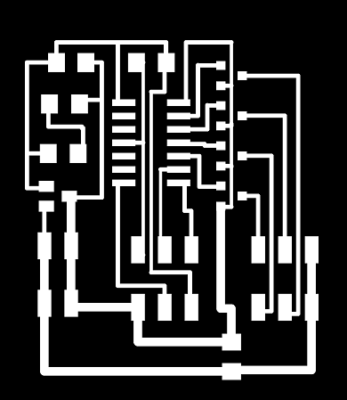
I decided to incorporate this extra capacitor into my own design. I also wanted to add an LED that would turn on whenever the board was powered. I found Kate Mytty's page from last year; and she drew her own schematic based on Neil's board as well. So I used her schematic as a guide to name the pins. Here are the schematic and board views, the traces and the boarder of my own board:

Here are the pictures of the list of components I used and the finished board:
Then, with Oliver's help, I tried to understand Neil's C code and play with the statements in the "while" loop a little bit. My board programmed successfully and I got the motor to turn!
Special Note: Neil commented in class that the initial problems listed above could be due to the fact that the voltage was exceeding the voltage limit of the motor. Therefore, it is important to check the datasheet of the motor before deciding what voltage to supply. Another possibility was that the high voltage kept resetting the microcontroller; that's why incorporating the capacitor helped resolve the problem.
I still have to figure out how to make the motor turn to a particular position then stop or pause, as this will be relevant to my final project. I will try to study the codes more closely and see how to make further modifications. I will also try the stepper motor example codes in Arduino and see what those can do.